In previous models, the energy saving operation function corresponded with the load state, and controlled operation to minimize loss of the motor itself. The newly developed FRENIC-Eco Series has shifted the focus from the motor to the inverter, recognizing that the inverter itself is an electrical product, and the new models are equipped with a new control system that minimizes the power consumed by the inverter itself (inverter loss) as well as the power loss in the motor itself.

Using this new system, energy savings is several percent improved over that of the previous models.
Kyoto Agreement, which was studied at the Conference on Prevention of Global Warming (COP3), was ratified by Russia in October 2004, and thereby put into effect on February 16, 2005. In the future, the related regulations are calling for a reduction in energy consumption of 1% or more each succeeding year, and therefore, we are aiming to build energy saving features into equipment as a whole.
FRENIC-Eco is the inverter equipped with the industry’s highest level of efficiency (low power loss).
Power-related data can be checked at the inverter unit’s keypad.

Even if a momentary power failure occurs, load inertia of a fan or blower, etc. is used to maintain the motor’s operation while the motor’s operating speed gradually drops, and enables the motor to restart operation without stopping.
(The motor may stop on occasion due to the load’s inertial moment.
If you desire to run a fan which the inverter is not currently running and which is turning free, this function will pick up on its motion regardless of the direction it is turning in and start it operating. Momentary switching is performed in the inverter from the commercial power supply and provides a convenient function when starting motors, etc.
Deceleration time is controlled to match the internal energy level generated in the inverter, and so deceleration and stopping is accomplished without tripping due to overload.
When there is pump operation accompanying “pressure drop” that occurs due to pressure loss or leakage, etc. in the piping, etc., or at times when the pump runs repeatedly to obtain a small volume of water, this function controls the pump’s operation, preventing it from being driven with the water volume below a predetermined level, and thus reducing wasteful pump operation and saving even more energy.
The inverter determines the load state of the connected motor and if it drops below a predetermined level, it judges that a “Low Torque” state exists and outputs a signal to that effect. In this way, any trouble that occurs in the equipment (such as a belt on a pulley breaking) can be grasped by the inverter.
If the frequency signals (0 to 10V, 4 to 20mA, multi-step speed operation signals, communications, etc.) that are connected to the inverter are blocked, signals are output as a “command loss,” indicating that a frequency command was lost. In addition, output frequency when the command loss occurred can be set in advance, so even if a frequency signal line to equipment is broken due to machine vibration, etc., machine operation can be continued uninterruptedly.
Inverters are equipped with the commercial line start function that enables switching between the commercial line and the inverter by an external sequence. In addition, inverters are equipped with two types of built-in sequence for operation with commercial line; i.e., Fuji’s standard sequence and the automatic switching sequence to the commercial line activated when the inverter alarm occurs.
Note: The latter sequence differs from the one for forcible switching to the commercial line during inverter breakdown.
If the load on a fan or pulley increases due some foreign object getting wrapped around the shaft, etc., and the inverter’s internal temperature rises suddenly or the ambient temperature rises to an abnormal level, etc., causing an inverter overload state, the motor’s speed is lowered, reducing the load and enabling operation to continue.
Low water level stop function, deviation alarm and absolute value alarm outputs have been added to the PID regulator which performs such tasks as temperature, pressure and flow rate control. In addition, an anti-reset windup function that prevents PID control overshoot as well as a PID output limiter and integral hold/reset signal provide easy-to-adjust PID control functions.
Signals can be transmitted to a higher level controller or PC by connecting digital signals to an inverter from different types of sensors, such as a float switch used to judge the level in a water storage tank, which serve as peripheral devices to the inverter. In the case of small-scale equipment, even if a programmable logic controller (PLC) is not used, information can be sent to a higher-level system easily.
Using the display coefficient of signals from devices such as flow rate or temperature sensors in air conditioning equipment, these signals can be converted into physical values such as temperature and pressure and displayed synthetically on the inverter’s keypad without making the use of exclusive flow meters or air flow meters.
When the inverter slows down and stops the motor, if the braking energy regenerated by the motor exceeds the braking capacity of the inverter’s main circuit capacitor, the inverter will trip. At such a time, if even a little excess energy trips the inverter, using this function you may be able to absorb the excess braking energy without connecting to a braking resistor.
– Motor condensation prevention function
Prevents condensation of the motor from occurring in cases where the surrounding temperature changes suddenly while the motor is stopped.
– Motor speed display with percent
The inverter’s keypad displays the operating frequency (Hz) or the motor’s rotational speed (r/min), but it can also display the maximum speed as 100%, so it is easy to get a grasp of the equipment’s operating state.
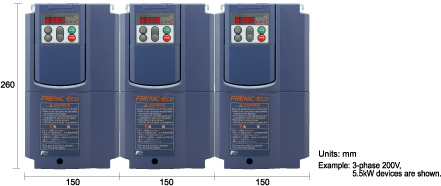
If multiple inverter units are to be used in a panel and the panel is designed accordingly, it is possible to mount these inverters side-by-side horizontally, so the panel can be designed to take up less space. (5.5kW or lower capacity inverters)